Description
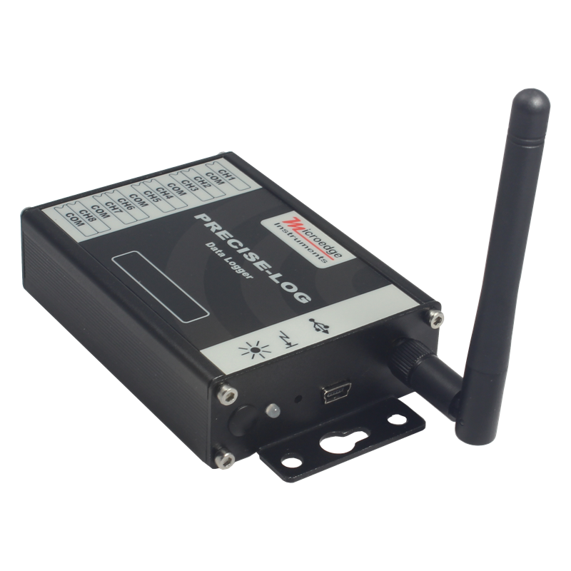
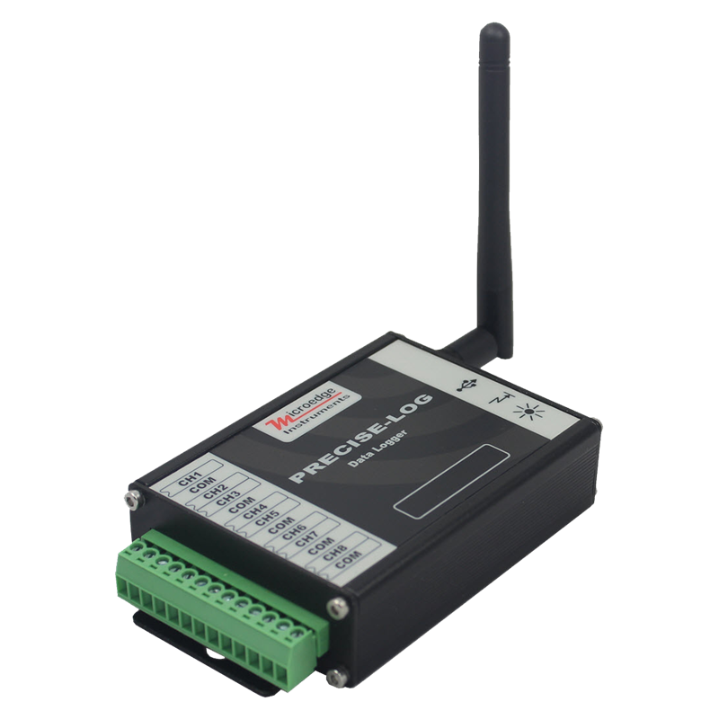
Product: Wireless Voltage Data Logger
Made by: MICROEDGE INSTRUMENTS (CANADA)
Series: PRECISE-LOG
Model: PL-VW
PL-VW is an 8-channel, battery powered, standalone and WIFI-enabled voltage data logger. The logger records eight external voltage sources and saves data in 8-MB memory.
Its aluminum enclosure makes it excellent in the harshest industrial environment.
Embedded WIFI module allows remote data monitoring and downloading.
16-bit ADC makes it well suited for science and laboratory applications where precise and accurate measurements are critical.
Simply power the logger in WIFI covered area and access it from your computer for configuration, downloading, graph viewing and more...
Features:
- 16-bit analog-to-digital converter
- 8 megabyte memory size
- Both USB and WIFI comm. interfaces with baud rate of 115200 bps
- Programmable input ranges (5 VDC, 20 VDC)
- Over 10 years of battery life
- Powerful software for configuration, downloading, plotting, analysis and alarm reporting
- Wide sampling interval selections (one second to 12 hours)
- Rugged aluminum enclosure
Modbus
From July 15th, 2019, Modbus TCP protocol will be added to all PRECISE-LOG series of data loggers. A Modbus master/client can read one or more Input Registers and Holding Registers available in a PRECISE-LOG data logger through Modbus TCP communications. The below specifications list all supported commands and available registers PL-VW data logger supports:
Input Registers:
An Input Register stores a 16-bit integer for a channel’s real-time reading. To read one or more 16-bit Input register data, use function code 4.
| Register |
Description |
Type |
Range |
| 0 |
CH0 Value |
Unsigned Integer |
0 - 65535 |
| 1 |
CH1 Value |
Unsigned Integer |
0 - 65535 |
| 2 |
CH2 Value |
Unsigned Integer |
0 - 65535 |
| 3 |
CH3 Value |
Unsigned Integer |
0 - 65535 |
| 4 |
CH4 Value |
Unsigned Integer |
0 - 65535 |
| 5 |
CH5 Value |
Unsigned Integer |
0 - 65535 |
| 6 |
CH6 Value |
Unsigned Integer |
0 - 65535 |
| 7 |
CH7 Value |
Unsigned Integer |
0 - 65535 |
Example:
To read CH2, CH3 and CH4's real-time values, a Modbus master device sends in the following command:
| Data(HEX) |
Description |
Note |
| 0001 |
Transaction identifier |
Fixed 2-byte value |
| 0000 |
Protocol identifier |
Fixed 2-byte value |
| 0006 |
Length(6 bytes are followed) |
2-byte value |
| 01 |
The device address |
1-byte value, don't care |
| 04 |
Function Code (read Input Register) |
1-byte value |
| 0002 |
First register's address |
2-byte value |
| 0003 |
The number of required registers (read 3 registers 0002 to 0004) |
2-byte value |
Holding Registers:
A Holding Register stores a 16-bit integer indicating a setting for the data logger. To read one or more 16-bit Holding Register data, use function code 3.
| Register |
Description |
Type |
Range/Equation |
| 0 |
Sample Interval |
0: below 1 second
>=1: sample interval in second |
0 - 65535 seconds |
| 1 |
Device Operating Mode |
0: logging stopped
1: logger is logging data |
|
| X0 |
CHX-1 Type |
0: Range#0 (0 to 20 VDC)
1: Range#1 (0 to 5 VDC)
2: Range#2 (-5 to +5 VDC) |
|
| X1 |
CHX-1 Enabled |
0:disabled
1:enabled |
If a channel is disabled, the reading is unknown |
| X2 |
CHX-1 Equation |
0: Range#0 Voltage |
Range: 0 to 20 VDC
Equation
O = 20 * I / 65535 |
| 1: Range#1 Voltage |
Range: 0 to 5 VDC
Equation:
O = 5 * I / 65535 |
| 2: Range#2 Voltage |
Range: -5 to +5 VDC
Equation:
O = 10 * I / 65535 – 5 |
| 3: Linear |
O = (LRH – LRL) * I / 65535 + LRL
Where:
LRH is Linear Range high value
LRL is Linear Range low value
You can get those values from SiteView |
Where X = 1,2,3,4,5,6,7,8
O = Output, I = Input Register Value
Example:
To read CH3's equation, a Modbus master device sends in the following command:
| Data(HEX) |
Description |
Note |
| 0001 |
Transaction identifier |
Fixed 2-byte value |
| 0000 |
Protocol identifier |
Fixed 2-byte value |
| 0006 |
Length(6 bytes are followed) |
2-byte value |
| 01 |
The device address |
1-byte value, don't care |
| 03 |
Function Code (read Holding Register) |
1-byte value |
| 002A |
First register's address (42 is 2A in HEX) |
2-byte value |
| 0001 |
The number of required registers (read 1 registers 002A) |
2-byte value |
Note:
- Modbus feature was added to firmware version 2.05 or above.To upgrade a data logger's firmware please refer to this link: How can I upgrade logger firmware?
- The age of an Input Register data is based the data logger's sample interval.If the logger has stopped logging or the logger's sampling interval is slower than five seconds, a request of Input Register data will initiate the sampling process and the new data will be available upon the next request.